 Essentially water within a transformer derives from two sources; either external, due to a damp environment or internal, due to thermal deterioration of the papers (hydrolysis).Therefore water can be dissolved within the oil or, more seriously, be absorbed into the solid isolation (papers) with an increasing probability of thermal damage, and bubble formation moving on to partial, low energy (D1) and high energy discharges (D2).
Simply treating the oil can reduce water content but it can not remove the water absorbed by the solid insulation (paper).
The best maintenance strategy is to prevent the papers decaying (closely related to the residual life of the transformer) by firstly avoiding water accumulation inside them.

Which treatment is right for you?

Sea Marconi carries out cellulosic insulation dehydration (papers) using two alternative processes
Direct dehydration
Direct dehydration of the transformer (papers) consists of heating the reels by circulating the oil.Subsequently, the transformer is rapidly emptied and put under vacuum.Then the transformer is partially filled maintaining the suction of the vacuum. The extraction of moisture occurs by cyclically repeating the heating and vacuum processes.
Click here for more details
2. Transporting staff, technological systems and tanks
3. Site preparation, and the hydraulic and electrical installation of the treatment systems
4. DEOSVISION® analysis before treatment (if any) – Before starting operations an oil sample will be taken from the transformer to determine the initial conditions of the oil-machine
5. Preparing the transformer for the vacuum – All accessories and components, which can not resist the vacuum (the expansion tank or anything else) are isolated by closing the shut-off valves or applying blind flanges
6. Heating the reels by circulating and heating the oil until the oil in the upper section of the caisson reaches a temperature close to or greater than 80°C
7. Rapidly removing the oil and preparing the transformer for the vacuum – The oil is quickly removed and transferred into a correctly sized tank until the reels are exposed
8. Applying the vacuum – After emptying the unit a vacuum is applied until a residual pressure of less than 10 mbar is obtained within the caisson. The vacuum is maintained until the reels reach a temperature close to 40°C, or, alternatively for at least 12 hours
9. Partial loading under the vacuum– The oil is reinserted into the caisson through the gate at the bottom, until the reels are completely covered, but at the same time the suction of the vacuum is maintained in the upper section.
During the loading step the oil is circulated through the degassing unit in such a way as to undergo degassing and dehydration within the vacuum
10. Repeating the dehydration cycle – Steps 6 to 9 are repeated until the amount of condensed water in 24 hours, the duration of the vaccumm, is less than 150 g per ton of cellulosic insulation
11. Final loading, and level/vent controls – Once the dehydration cycles are completed, the transformer is completely filled
12. Physical decontamination treatment (degassing and dehydration under a vacuum) by continuous circulation in a closed circuit
13. Monitoring the process parameters – Sea Marconi is committed to daily monitoring the main parameters of the treatment, and in particular, the amount of water extracted and condensed as well as the oil discharge voltage.
14. Replacing the desiccant salts in silica gel;
15. DEOSVISION® analysis at the end of intervention – At the end of the treatment an oil sample will be taken from the transformer to control and certify that the objectives have been reached
Criteria that stop treatment
The following table shows key values depending on the mass of the cellulose insulating material contained in power transformers, which are useful in determining criteria that stop the process
| Transformer power [MVA] |
Mass insulating material [ton] |
Stop treatment if condensed water extracted in 24h [ml] |
| 63 | 2,5 | < 375 |
| 100 | 3,5 | < 525 |
| 160 | 5,0 | < 750 |
| 250 | 6,0 | < 900 |
| 370 | 8,0 | < 1200 |
| 400 | 10,0 | < 1500 |
Duration is expressed in weeks
Results and technical guarantees
| Properties | Test Method | Value |
| Dissolved Water (mg/kg) | IEC 60184 | < 10,00 (1) |
| Discharge Voltage (kV) | IEC 60156 | > 70 |
| Water extracted (ml/gg) | Volume | < 150 ml/ton |
(1) Withdrawal at a temperature between 40 and 60°C
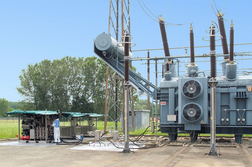
Indirect dehydration
The indirect dehydration of the transformer (papers ) consists in heating the oil (and therefore the reels), to help the water in the papers transfer into surrounding oil. Once the water has moved into the oil it can be removed through the degassing and dehydration systems. Water movement from the papers to the oil is aided by heating it: the higher the temperature the higher the solubility of water in the oil. For this reason, the indirect dehydration is performed while keeping the transformer in service, under tension and filled.
Click here for more details
2. Transporting the decontamination modular unit (DMU)
3. Hydraulic and electrical installation and set up
4. DEOSVISION® analysis before treatment – Before starting operations an oil sample will be taken from the transformer to determine the initial conditions of the oil/machine
5. Physical decontamination treatment by degassing and dehydration in a vacuum by continuous circulation in a closed circuit. If the transformer is not kept constantly full during the treatment or if the load is low (compared to the nominal load), the treatment system will be linked to one or more supplementary heating units in order to obtain the predetermined temperature requirements.
6. Monitoring the treatment parameters.Sea Marconi is committed to perform weekly checks on treated equipment, and the parameters of the oil by means of sampling and laboratory analysis.
The results are transmitted to the customer on a weekly basis.
7. Level and vent controls
8. Replacing the desiccant salts in silica gel
9. DEOSVISION® analysis at the end of the treatment – At the end of the treatment an oil sample will be taken from the transformer to control and certify that the objectives have been reached
10. Removal and transportation of the Sea Marconi treatment units (DMU)
Length of service
The following table shows running times for a general idea.
| Oil mass [ton] |
Maximum nominal voltage | ||
| ? 63 kV | ? 130 kV | ? 225 kV | |
| 5 – 10 | 4 | 5 | 6 |
| 10 – 20 | 6 | 7 | 8 |
| 20 – 30 | 8 | 9 | 10 |
| > 30 | 10 | 11 | 12 |
Duration is expressed in weeks
Results and technical guarantees
| Properties | Test Method | Value |
| Dissolved Water (mg/kg) | IEC 60184 | < 10,00 (1) |
| Discharge Voltage (kV) | IEC 60156 | > 70 |
| Water extracted (ml/gg) | Volume | < 250 |
(1) Withdrawal at a temperature between 40 and 60°C